1915 Stivers Metal Lathe Restoration

Background
This lathe belonged to my great-grandfather Greg Blackwood, who was a machinist and toolmaker back in World War 1. After he left high school, he attended Stevens Institute of Technology in Hoboken NJ for about a year (back in the days when school was actually reasonably priced). He feared being drafted and didn’t like the idea of dying in brutal trench warfare, so he enlisted as a machinist, stationed on a ship somewhere off the shores of Europe. He wasn’t really a draft dodger – he just felt that he could better serve his country with his technical skills.
From what information I can gather by word-of-mouth from my grandparents, he attended a technical high school and for his final project, he and another student chose the necessary parts to build this lathe, and got it 80% finished. I can only guesstimate the date at which he did this, but based on the history I am willing to bet that he built this around 1914-1915. The remaining 20% of the work was for me to do, 100 years later. I think that it is especially cool that I am finishing a project that was started over a century ago. It’s got a heritage factor to it.
The Cabinet
Before I could do anything else, I needed a bench on which to rest the lathe and house the motor, and store any tools like cutters and cutting oil. For this, I re-purposed an old wooden cabinet. As utilitarian and inexpensive as it was to do this, I probably would have been better served with a sturdier metal cabinet, which would have been more resistant to vibration. With the wooden cabinet, any vibration from the motor and any slight imbalance of the pulleys can be exacerbated by the relatively flimsy wooden cabinet. This surely will cause some deflection of the cutting tool and result in a less accurate part and potentially worse surface finish as the cutter oscillates, manifesting itself as a rougher surface. The extent to which this vibration affects the surface finish I am not sure of – but in general, any amount of vibration will decrease accuracy. I stiffened the cabinet up by mounting some 4″x4″ wooden posts in the corners on the inside of the cabinet. The addition of this reinforcement helped considerably, but vibration does still exist.
Powertrain
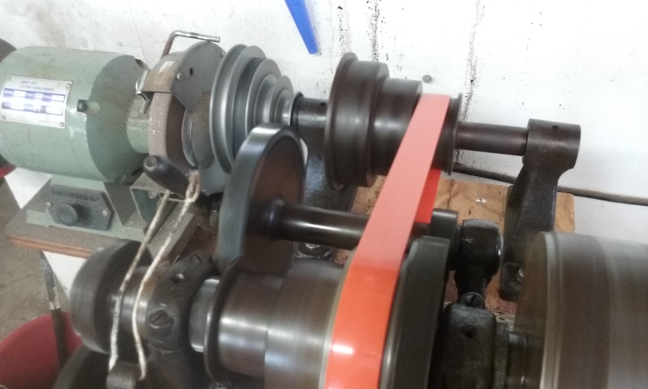
The next step was the acquire an electric motor, which are pretty expensive these days. To save some cash, I took the 1 HP motor off of an old 1950’s Sears air compressor, took off the pulley, and replaced it with a zinc adjustable-speed V-belt pulley to match the pulley on the rear pulley assembly (which came with the lathe). In order to properly tension the V-belt, I mounted the electric motor on a hinged plate inside the cabinet. The weight of the motor provides sufficient force to tension the belt. From what I have read, there is indeed a relationship between the amount of tension in the belt and the lifetime of both the belt and the bearings attached to the pulleys. I do not know the numerical value for the amount of tension that yields optimal belt lifespan. As a hobbyist who cranks out only a dozen or so parts per year, I do not think I will be running this lathe for long enough to really worry about belt lifespan.
Welding Urethane Flat Belts
This lathe is pretty darn old, so it utilizes flat belts, which made it a rather versatile lathe – in old factory setups where safety wasn’t the greatest concern, long overhead line shafts would run parallel to the factory ceiling, and a long flat belt would run down from the line shaft to the lathe. These were used up until the early 20th century, but it seems that small electric motors had become ubiquitous enough that my great-grandfather did buy the rear pulley assembly for use with small electric motors.
Urethane flat belts seemed to be the most economical option, as an alternative to leather flat belts. Buying pre-made urethane belts was significantly more expensive than buying a single length of unwelded flat belt, so I saved some money by welding it myself with a blowtorch and a piece of sheet metal (the real welding kits cost incredibly amounts of money, and I wasn’t prepared to pay $1000 for a tool I will only use once).
Welding the belt is fairly straightforward. Take a piece of steel sheet metal (the thicker the better, as it will hold heat for longer to give you more time to work) and clamp it in a vise. Heat the sheet metal with the torch (NOT red hot, that is waaaaay too hot), then when it is at the right temperature of about 450 degrees Fahrenheit, butt the two free ends of the belt material into the metal from either side for about 5 seconds until you start to see the urethane melt, then quickly and carefully butt the two ends of the belt together, and hold for about 15 seconds until it cools. It’s a tricky process that takes some experimentation, as the temperature is extremely important. Too cold, and the urethane will not melt sufficiently to form a good bond. Too hot, and the urethane begins to burn and chemically change, and will no longer bond properly. I did use a non-contact infrared thermometer to ensure the temperature of the sheet metal was at 450 degrees Fahrenheit, which resulted in a fairly good bond. A weld done with a proper tool, (i.e. a temperature regulated heating element), would most likely be stronger and hence last longer, but I have had great success with this cheap method, a little finesse, and a $3 piece of belt.


Accuracy and Precision
I don’t really possess the correct tools to determine the accuracy nor the precision of the lathe. It does use journal bearings that must be lubricated quite frequently. In theory, the thin film of oil that allows these journal bearings to rotate freely can vary in thickness depending on how much pressure is put upon them. However, I think such deflection is likely negligible in comparison to any deflection in the tool post and the carriage if I am taking particularly deep cuts. Accuracy should improve once I further reinforce the cabinet to suppress most of the vibrations from the motor, or entirely replace the cabinet with a steel one.
Exciting Stuff / Accidents
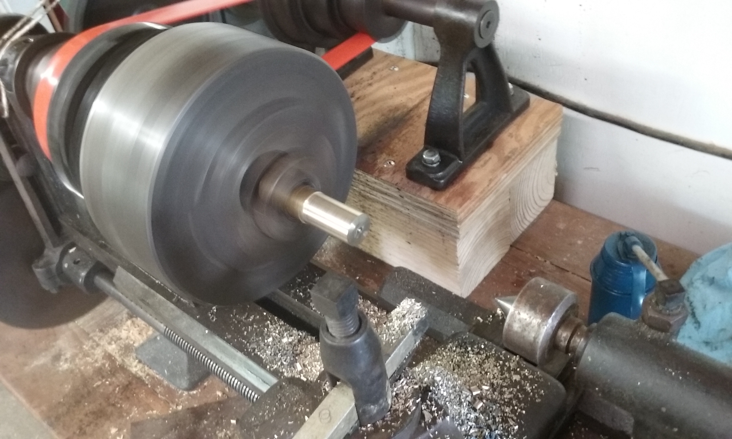
The lathe does have a carriage with auto-feed that runs from right to left. There is no end-stop, however, so if you aren’t careful, the carriage will happily continue moving closer and closer to the spinning chuck until you start to hear this quiet clicking sound that quickly gets much louder, and before you can even think “What is that sound?” the chuck has snapped the cutting bit and is gouging into the tool post, until the chuck stalls while the belts keep spinning furiously until you can find the off switch. Although I was being careful, it can be difficult to see the teeth of the chuck as they spin at 1000 RPM. It wasn’t fun to crash the lathe, but seeing how much kinetic energy this heavy steel chuck has at full speed has gotten me to think more seriously about implementing safety mechanisms such as a large red kill-switch, as well as an enclosure for the gears and pulleys.
Improvements for the Future:
Safety
I need to build a safety enclosure to cover up the pulleys and the gears. If someone were to get a finger or a hand caught in one of those gears, the machine would take it right off without hesitation.
Secondly, I need to install an end stop for the carriage. I’ve crashed the cutting tool into the chuck once already… it wasn’t pretty.
Accuracy
Wooden tables aren’t quite stiff enough for this task. Either reinforce it, or build a new table out of steel.
Additionally, I need to adjust the carriage to eliminate any slop that is present.
Last updated 12 February 2017.